Comments? email to
![]()

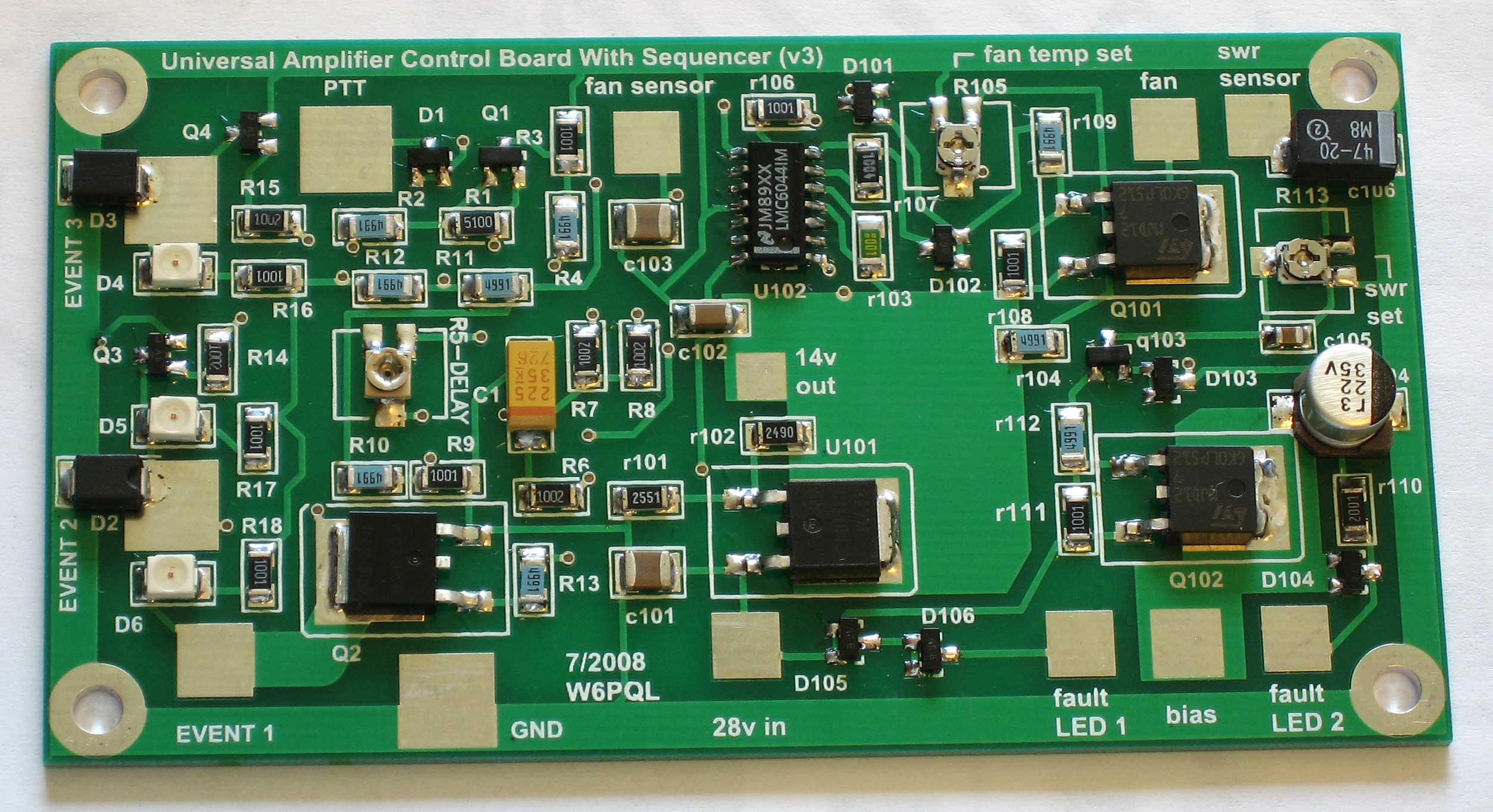
This board combines the functions of a relay sequencer, amplifier bias switch, temperature-controlled cooling fan and a high-VSWR cutoff switch. It basically combines the functions of several different boards onto one, saving some space and wiring.
Although it was designed for 28v amplifiers, it can be used on 12v systems as well, or at any voltage in between.

A high-resolution photo, suitable for component placement during assembly, is here.
A complete schematic follows at the bottom of this page, but let's look at the various functions in pieces:

The first section is the sequencer. This particular one will handle three events at push-to-talk (PTT).
The first event is usually used to operate the antenna relay(s) and turn on a cooling fan.
The second, triggered about 50 milliseconds later, brings the amplifier on-line (turns on the bias).
The third, happening 50 milliseconds after the second, is optional, and might be used to enable a transverter.
All of these events unfold in reverse order (at intervals) when PTT is released.
The length of the timing intervals is adjustable.

OK, since the first event turns on a cooling fan, let's look at the fan controller next.
Most inexpensive computer-style cooling fans are 12v, so we'll drop the 28v down with a regulator (U101). The 14v output also feeds the control IC, which is a 16v (max) device.
U102 can be connected to a sensor, typically a thermistor mounted on the heat sink of the amplifier. R105 sets the trigger temperature to start the fan, and I usually set this for a heat sink temperature of 100f. Once the temp is below this level, U102 shuts off the fan.
PTT (event 1 through the sequencer) will override this control, keeping the fan on during the
entire transmit cycle, even if the heat sink is below 100f.
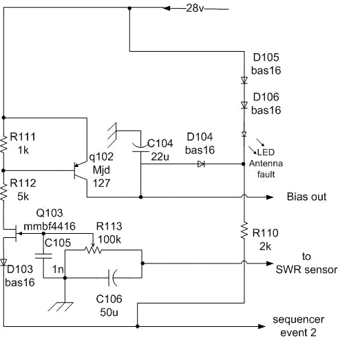
This last section shows the bias and VSWR cutoff switches. Bias is turned on by the sequencer (event 2), after the antenna relays have been switched. Q102 is the gate, and is capable of supplying an amp or more of bias current.
Q103 has a special job; but most of the time, it does nothing.
However, if you connect it's input to a diode detector (negative-going) that senses the reflected power from your antenna, it can cut off the bias to the amplifier. I usually set the sensitivity (R113) to trigger at 3 to 1 VSWR.
The LED (usually mounted to a panel) will light if Q103 shuts
off the bias while transmitting with high VSWR.
This is the complete schematic
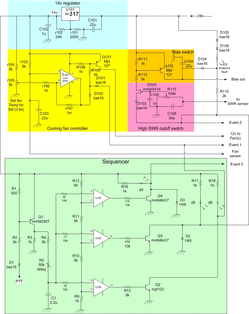
Note: for 12v operation, do not install U101; jumper the 28v pad to the 14v pad, and change R111 to 2k.
One final note: The on-board regulator will only be able to supply about 150ma for running a fan; if you will use multiple fans, or if your fan draws more current than that, you'll need to use a current booster between the output of the control board and the fan. This booster is not necessary when the board is set up for 12v operation (fan current can be up to 2a or so). The two schematics below are examples of current booster circuits:
