Comments? email to
![]()


Related articles: Microwave L.O. Crystal Oven Controller and MIcrowave Marker.
The OXCO shown here combines the benefits of a low-noise butler oscillator with a temperature controller, and can use 5th or 7th overtone crystals in the 90 to 199 MHz range. The oven temperature is fixed at 50C, though it can be set to pretty much any temperature required.
Because the temperature controller and oscillator are on opposite sides of the same board, the controller has maximum thermal influence on the crystal and all of the other oscillator components. This tight coupling allows the oscillator to reach microwave communications stability in less than 3 minutes from a cold start, and is stable enough for digital modes in less than 5.
I originally made this for a transverter I was building, and because it worked so well, I began to replace some of my other L.O.'s with it. It easily drives the multiplier chains in the DB6NT and DEMI units I use here. An example of it's use can be seen in the 100w 23cm Transverter article.
As a source for a weak-signal marker, it can also be used to drive a simple MMIC multiplier, (which fits easily into the same enclosure) providing strong signals audible all the way through 10 GHz.
Power requirements for the OCXO are 8 or 9v regulated at 50 to 250ma (it draws about 100 ma when the oven reaches operating temperature).

 The
oscillator side of the board is shown on the left, and the oven controller side
on the right.
The
oscillator side of the board is shown on the left, and the oven controller side
on the right.
The crystal fits into a slot at the edge of the board and is
positioned to straddle both sides as shown in this inset: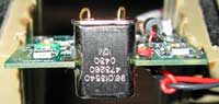
On the oven side, the temperature sensor (R12B) and the heater resistors are located near the crystal. Note that the sensor is installed at one of three possible locations. There's a bit of black magic here, as sensor placement often has considerable influence on control. Some experimentation with location may be necessary for best results.
Tune-up of the oscillator is pretty easy; with a voltmeter connected to the test point (TP1), the peak trimmer capacitor is tuned for max reading, about half a volt. The only other adjustment is the net trimmer, which is adjusted to trim the oscillator right on frequency.
 The
enclosure used in this example was made from .015 tin sheet. The top and
bottom lids were formed from the same material.
The
enclosure used in this example was made from .015 tin sheet. The top and
bottom lids were formed from the same material.
Suspended into the dead air space of the box, the board is secured to the sides using solid wires soldered to the corners as shown (it doesn't look securely fastened, but it really is). This was done to minimize heat loss into the enclosure. As an alternative mounting method, there are two 1/8" mounting holes in the board for use with 4-40 hardware.
A TO-220 regulator chip, tab soldered to the inside of the box (left wall), is supplied 12v from a feed-through capacitor, and delivers the recommended 8v to the board.
The output coax passes through a small hole drilled into the
wall, and the shield is soldered there as it passes through. In this example,
the output is being taken from the 10 mw pad. The auxiliary output limiting
resistor (RL) was not used.

Removing the cover on the other side reveals the temperature controller side of the board.
Once the entire assembly has been tested, an access hole can be drilled into the lid covering the oscillator side (for adjustment of the frequency net trimmer), and both lids can be secured by spot-soldering to the enclosure.
For installing the completed box into other equipment, I used a couple of solder lugs soldered to the enclosure (as shown in the first picture at the top of the page).
This is just one example of an "economical" enclosure...a small aluminum box, or other product (such as a die-cast box or a brass box) will work just as well.
The whole thing measures 1.75" x 1.75" x 1" tall as shown, and could be made smaller if necessary.
Detailed assembly instructions can be viewed here:
