Comments? email to
![]()

![]()
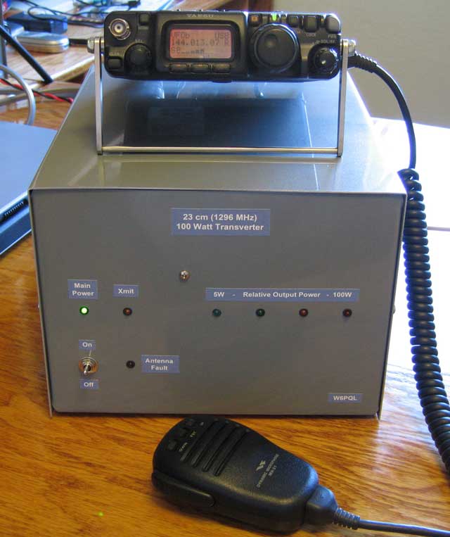 Here's
a killer 1296 rover setup --- a small (FT-817) I.F. radio driving a 100w
transverter with a 1db nf front end.
Here's
a killer 1296 rover setup --- a small (FT-817) I.F. radio driving a 100w
transverter with a 1db nf front end.
The transverter shown here runs on 12v (but it does need 36 amps), and is a hybrid using a DB6NT 1w mini-transverter driving the 100w "brick" amplifier shown in the previous article.
It contains some unique features, such as an LED output power meter, a temperature-controlled cooling fan for the PA unit, ALC feedback to the driving radio, a sequencer and an OCXO local oscillator.
I found the OXCO to be necessary, as the DB6NT transverter, good as it was, had a temperature-sensitive L.O. and drifted as much as 200Hz during a single transmission. With the OXCO modification, it now moves less than 10Hz after a 15-minute series of transmissions.
The transverter measures 8"W 6"H 10"D.
 This
picture shows the layout of the left side (top cover removed). Shown are the
sequencer, Dow Key antenna switch with it's
pulse latching driver board, the
outboard OCXO, and the DB6NT
mini-transverter.
This
picture shows the layout of the left side (top cover removed). Shown are the
sequencer, Dow Key antenna switch with it's
pulse latching driver board, the
outboard OCXO, and the DB6NT
mini-transverter.
There are three fuse blocks located on the inside of the back
panel. I fused the two sides of the PA separately to different pins on the power
connector, and used a third fuse for the rest of the transverter. This allowed
me to use two 20a power supplies to run it, instead of a single 40a supply,
which I did not have. Of course, if one wants to use a single supply, the two
supply cables can be connected together at the power supply.
Here's a close-up of the small ALC board, mounted directly to
the I.F. input connector. This board is used to limit the drive power from the
transceiver to 2w max.
 On
the other side of the separating partition is the 100w PA assembly.
On
the other side of the separating partition is the 100w PA assembly.
Above it, mounted to the partition panel, is the fan controller board. This little board turns the fan on during transmit, or whenever the heat sink temperature is above 95F. It's temperature sensor is on the little board mounted to the heat sink just above the input coupler that is facing us.
The power meter driver board is mounted in the middle of the
horizontal aluminum plate on the top of the PA, and drives the LED indicators on
the front panel.

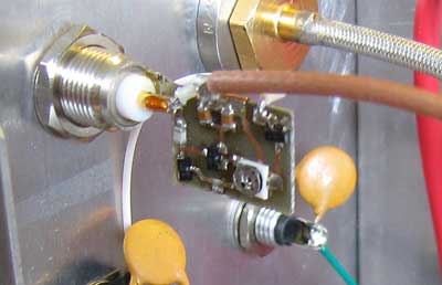
Here's a close-up of the RF sampling probe for the power meter driver board. I used a 1/2wl piece of Teflon coax with it's shield soldered to the output coax shield, and the 1/4" probe hovering above the output port of the output coupler as shown.
I left the Teflon insulation on the center conductor (makes a
better capacitor and guards against an accidental short). This provided several
milliwatts of RF to the detector located on the meter driver board.
 The
rear panel has the necessary connections for power supply, driving radio, and
even an external LNA, if desired.
The
rear panel has the necessary connections for power supply, driving radio, and
even an external LNA, if desired.
The fan draws air in and pushes it through the heat sink
cluster of the PA. Warm air is expelled out of the top vent.
Well, that's about it...schematics follow below.