| This first attempt was modeled with AppCad,
a free program available on the Agilent Technologies web site.
design center = 1280 MHz (because I aligned the adjacent microstrip traces center-to-center, I corrected the lengths from AppCad by the width of the adjacent branch lines) The resulting measurements indicate good isolation and port tracking. The difference in port coupling factors needed some work, though, as they were .4 db apart. Not bad, but I thought they should match up better. |
 |
| So, I applied a design correction using the Microwaves101 unequal
split calculator.
design center = 1280 MHz The results were better, but clearly I needed more correction. And what's with the isolation curve moving down from the design center? More on that in a bit... |
 |
| design center = 1280 MHz 33.3 ohm = 104 x 1279 (1212+67) 44.5 ohm = 67 x 1344 (1240+104) 50 ohm leaders = 55 x 187 (additional v6 adjustment using -1 as correction in formula to bring the main and aux coupling factors closer together) OK, nice port tracking, and the coupling matches within a tenth of a db. But look at the isolation, it moved down even more from the design center??? |
 |
| After pondering this a bit, I finally figured it out; as I
widened the transmission lines to adjust coupling ratios, my connection
to the 4 ports became less precise (this was caused by my placement of
the 50 ohm lead-ins). Essentially, this error caused the horizontal
lines to become long, and the vertical ones to become short. Duh!
|
 |
| Once I corrected for this, all was well, and the device
behaved as predicted, with excellent performance over the entire 23cm
band.
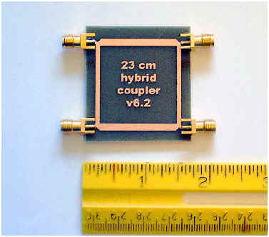
Clicking the picture below will provide artwork to scale in .pdf format.
|
 |

