 I
re-designed the original board to minimize unused copper areas, as these spots
must contain many vias to ground them to the opposite side to keep them 'quiet'.
I
re-designed the original board to minimize unused copper areas, as these spots
must contain many vias to ground them to the opposite side to keep them 'quiet'.
I
re-designed the original board to minimize unused copper areas, as these spots
must contain many vias to ground them to the opposite side to keep them 'quiet'.
At the same time, I noticed that on all previous boards, the main matching capacitors ran warm; while failure of these components is rare, I realized that short stubs of 10 ohm coax (pretty much indestructible stuff) would serve well as the matching capacitors.
The first capacitor is the longer coaxial stub shown here; it's 110mm long, and it's capacitance is 35pf. The second shorter stub is the other matching capacitor, 50mm long and 15pf. These values provided the best match with the revised board, which will work with either the Freescale MRFE6VP1K25H or the NXP BLF578XR or BLF188XR LDMOS devices.
Here's the most current schematic
Assembly instructions are listed below:

The first components to mount are the capacitors.
The 470pf MC18 capacitors are installed in pairs at the four locations shown. Mounting them on their thin edge helps to balance the currents in the pairs.
Then mount the two 1206 size 1000pf capacitors, the two 2.2uf and two 220uf
electrolytics.
![]() TC-12 coax transformers are next. The position of the connection point at the
drain traces will affect the match; the loop at the left should be lined up with the
transition line where the trace transitions from wide to narrow, on the side of
the transition toward the top of the photo. The
loop on the right should be placed right up against it on the other side of the
transition as shown.
TC-12 coax transformers are next. The position of the connection point at the
drain traces will affect the match; the loop at the left should be lined up with the
transition line where the trace transitions from wide to narrow, on the side of
the transition toward the top of the photo. The
loop on the right should be placed right up against it on the other side of the
transition as shown.
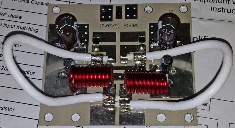
Install the two 10-turn VDD drain inductors
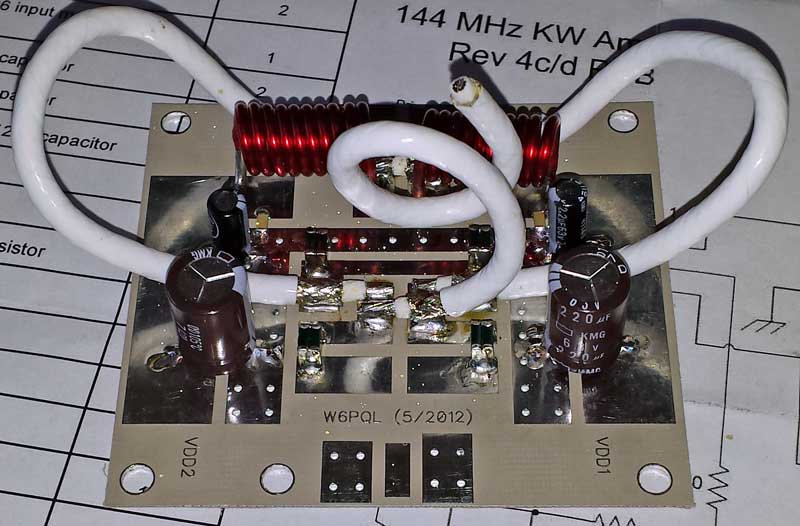 The 35pf
coaxial capacitor is next, formed in a way that keeps the open end away from
other components.
The 35pf
coaxial capacitor is next, formed in a way that keeps the open end away from
other components.
 The
RG142 balun is next.
The
RG142 balun is next.
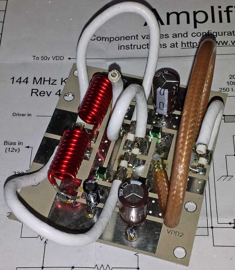
 The last
component on the output board is the 15pf coaxial capacitor. Position this part
so the open end is away from other components.
The last
component on the output board is the 15pf coaxial capacitor. Position this part
so the open end is away from other components.
This is the completed output board.
 Except for the input transformer, mount all input board components. The bias
has been set up for 12v feed. See the
assembly instructions for the 500w 70cm amplifier for other bias feed
configurations.
Except for the input transformer, mount all input board components. The bias
has been set up for 12v feed. See the
assembly instructions for the 500w 70cm amplifier for other bias feed
configurations.
 Mount
the input transformer. It must be soldered to the board at the 5 points shown.
Mount
the input transformer. It must be soldered to the board at the 5 points shown.
Slide the boards under the transistor tabs (transistor should have been
previously flow-soldered to a copper spreader).
Here is a video showing how to flow-solder your LDMOS to the spreader.
Here is the drilling template for the spreader.
Secure the boards to the spreader with 4-40 x 3/16 screws and flat washers. Do not over-tighten.
Use some liquid flux, and solder the boards to the tabs as shown.
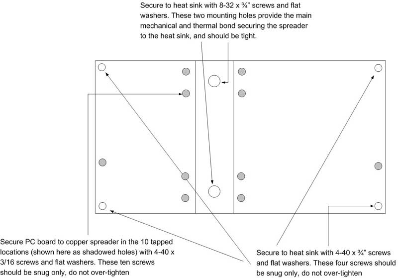 Fasten
the spreader to a suitable heat sink using the guide on the right. Use a
very thin coating of heat sink compound between spreader and heat sink (too
much, and it will actually impair heat transfer).
Fasten
the spreader to a suitable heat sink using the guide on the right. Use a
very thin coating of heat sink compound between spreader and heat sink (too
much, and it will actually impair heat transfer).
Turn on the 50v main supply voltage, but not the bias; there should be no current drawn
Turn on the bias and note the idling current drawn from the 50v supply. Adjust IDQ for 2 amps. Note: the current drawn by the bias supply (usually12v) is not what you are measuring here...you must measure the idling current (IDQ) the LDMOS draws from the 50v supply.
Shut off the power supply, and remove current limiting.