 A
A The attenuator resistors supplied in the kit are for the standard 1kw forward, 100w reverse full-scale power levels. Resistor values (and their part numbers) for other power levels are listed at the end of the technical article, and can be purchased from any of the major distributors.
Assembly time is about 1 hour and 15 minutes, 25 minutes of which is spent winding the two transformers. Following the assembly guide in the recommended order will provide the easiest assembly experience.
A
 Install
all of the parts except for the transformers and their coupling loops.
Install
all of the parts except for the transformers and their coupling loops.
Note that R1 is no longer used; R1 and R2 used to be a pair of 110 ohm 1w
resistors in parallel, but these have been replaced with a 56 ohm 2w part loaded
at R2.
It should be noted the default output polarity of the diodes used as
detectors is negative (an old commercial standard). If positive output is
desired, the diodes should be mounted upside-down.
Time to make the transformers. Locate the #28 magnet wire and the two ferrite cores; the T1 core is the smaller one. Recently it was reported the T2 core was saturating and ran too hot in high duty cycle modes like RTTY, so it became necessary to use a larger core at T2. If you have one of the earlier kits, and would like to upgrade to the larger core, contact me and I'll send it to you. This core is made by Laird, their p/n 28B0562-100.

Magnet wire will be used to wind 33 turns on each core. Using 25 inches of #28 magnet wire, wind the T1 transformer.
Pass the wire through the bottom of a core until each end is the same length. Begin winding by passing the first turn through the top of the core to the right of the previous one.
There are two turns on the core shown here (the turns are counted by the number of times the wire passes through the center of the core).
Pull the wire up against the outside of the core, and pass it through the
center to the right of the previous turns. Keep the turns close to one another
so you'll have room for all of them. When you have about an inch of wire left on
one side, turn the core over and wind the rest of the turns on the other side.
 Your
completed transformer should look like this.
Your
completed transformer should look like this.
Use the same technique and 48 inches of #28 magnet wire to wind 33 turns onto
the T2 core.

These next two photos show how to mount transformer T1.
Pass a 4 inch cable tie through the bottom of the board into one of the two holes at the T1 location. Capture the bare center of the transformer between the two ends of the wiring, taking care not to capture any of the turns.
Pass the cable tie through the top of the board into the second hole, into
the tie lock, and pull it snug. Trim away the excess tie material from the lock.


Using another cable tie and the same method, fasten the T2 transformer into position as shown in this photo.
Trim and tin the magnet wire on T1; the ground lead will come from the side of the transformer closest to the bottom of the photo (as you see it here). Solder it at the ground via just to the right of the transformer. The other lead is soldered to the pad at R1/R2.
Trim and tin the magnet wire on T2. the ground lead will come from the side of the transformer closest to the left of the photo (as you see it here). Solder it at the ground via just to the left of the transformer. The other lead should be soldered to the main trace...take care to route this lead low and away from the left side of the core.
 Prepare
the T1 transformer coupling loop by removing 1/8" (3mm) insulation from both
ends of the 1 inch piece of #16 Teflon wire. Tin the ends, and form
approximately as shown.
Prepare
the T1 transformer coupling loop by removing 1/8" (3mm) insulation from both
ends of the 1 inch piece of #16 Teflon wire. Tin the ends, and form
approximately as shown.

Pass the wire through the center of T1 and solder onto the large traces as
you see it here. The wire should pass through the center of the core just above
the tie-wrap band.

Locate the 2 inch piece of #22 magnet wire, and tin the ends. Insert this
wire into the 1.5 inch piece of Teflon tubing. Solder one end to the pad at
R5/R6. Pass the other end through the center of the T2 core and solder it to the
pad at R1/R2.

You're all done, but I want to leave you with a little 'black magic' trick here.
I've never seen a problem with directivity from 1.8 through 30 MHz, but it will almost always measure too low at 6 meters. The symptom will be a slight reverse power reading when there is no reverse power present. To correct this, I had to crowd the turns on T2 over to the left side as you see it done here, leaving about 10 or 15 turns crowded to the right side. The position of the wire passing through this core also has a large effect on the directivity. Once the adjustments are optimized, put a small amount of silicone sealant across the top of the core to keep the turns in place...I over-did it a bit as you can see in the photo, you don't need to use as much as I did on this one.
The easiest way to measure the directivity is to connect your transmitter to the input, a good dummy load to the output, and measure the voltage at the fwd and rev pads. With 750mv or so on the fwd pad, there should be no more than 25mv on the rev pad, assuming your dummy load has an swr less than 1.1 to 1.
This is more easily measured with a network analyzer connected to the R5/R6
pad, but the
transmitter/dummy load method will work for those not having access to such
an instrument, it's just more difficult and time-consuming to do that way.
Note: the following instructions for connecting into and out of the dual directional detector board show how to do it on the HF low pass filter assembly, which uses the same method.
 Secure
two solder lugs as shown here using the 4-40 machine screws provided; leftmost
photo is top side, rightmost photo shows the two locking nuts on the other side
securing the lugs.
Secure
two solder lugs as shown here using the 4-40 machine screws provided; leftmost
photo is top side, rightmost photo shows the two locking nuts on the other side
securing the lugs.
 Using
a pair of needle-nose pliers, bend the ends of the lugs vertical as shown. With
the lugs formed in this way, there will be considerable strength in both the
vertical and horizontal planes.
Using
a pair of needle-nose pliers, bend the ends of the lugs vertical as shown. With
the lugs formed in this way, there will be considerable strength in both the
vertical and horizontal planes.
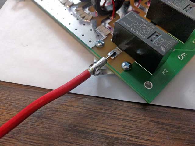
Shown here is RG402 coax, though you can use any coax (such as RG142) capable of handling the power.
Prepare your coax by removing 20mm insulation covering the outer conductor.
Next, remove 10mm insulation covering the center conductor.
With the center conductor laying on top of the board and soldered to the board trace, taking care not to move the coax, position the lugs against the sides of the outer conductor and solder them to the outer.
Repeat this procedure for the other RF connection.