Comments? email to
![]()


After some coaxing from 33cm EME enthusiasts, I developed this 33cm RF deck based on the NXP reference design. It uses the same MRF13750 LDMOS used in this 600w 23cm amplifier.
These RF decks are now in stock and available to order on the parts page.
This is the schematic for the RF deck:

The table below lists the first eight decks I assembled (not in the order they were built). Drive power was 6 to 7w:
| # | output power (w) | amps @ 50v |
| 1 | 780 | 25 |
| 2 | 770 | 25 |
| 3 | 750 | 24 |
| 4 | 740 | 24 |
| 5 | 740 | 24 |
| 6 | 730 | 24 |
| 7 | 710 | 23 |
| 8 | 680 | 23 |
 So
naturally at least one complete amplifier had to be built, and this one is
pretty much a clone of the 23cm version.
So
naturally at least one complete amplifier had to be built, and this one is
pretty much a clone of the 23cm version.
At 902MHz, the gain is a bit higher than 1296...this model only required 4 to 5w drive for 600 out.
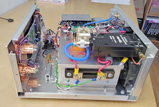
The next few photos show the layout of the various components in the interior of the amplifier, including the rear panel.
Wiring diagrams and other info on this unit are here.
 Top view:
Shields cover the control board and dual detector board. The large black object at upper right is a surplus 30db Narda dual directional coupler used to sample FWD and REV power levels for the control board and bar graph displays.
 Mounted
on the left side of the heat sink (just under the control board shield) is a
short-circuit proof 28v regulator.
Mounted
on the left side of the heat sink (just under the control board shield) is a
short-circuit proof 28v regulator.
This regulator is fed from the 50v rail and is current-limited to about 1.5A, enough to feed the 12v regulator on the control board. This provides two lower voltage sources for:
28v - For feeding any 28v relays (for external LNA or antenna switching) and the control board 12v regulator. Because the 28v regulator has short circuit fold-back protection, thus the 12v regulator is also immune to damage from shorts on the 12v rail.
12v - For feeding the control board, bar graph displays, an LNA and any 12v relays if those are used instead of 28v models.

This shows the rear of the front panel panel, containing the bar graph displays, switches and meters with their shields.
The two Molex connectors are disconnects allowing the front panel to be removed should any servicing be required.
 On
the right side of the heat sink is the ammeter shunt.
On
the right side of the heat sink is the ammeter shunt.
Some of the other components are mounted on the floor plate (left side).
 Layout
of the rear panel
Layout
of the rear panel