
First, let's load the module PC board(s). You'll need to refer to the schematic and the parts identifier, then perhaps watch this video for examples and suggestions on how to load and pre-test your board. Windows Media Player run in full-screen mode does a pretty good job with good resolution. You'll need a broadband connection to view this online; you can also download the file (it's about 42mb) and play it locally.
A loaded board is shown below with temporary wires attached for preliminary functional testing.

With the new board designs (rev 3 and 4), there was a curious change noticed in the output match. Given that I used a Mosfet module from a newer lot number than before, it is also possible that Mitsubishi made the change.
Please note the different position of the output coax in the picture to the right, shown on a rev 3 board. On this board, the compensation stub was eliminated for a proper match. This is accomplished by taking the output from the end of the trace, thus eliminating the stub.
A solder lug is used for the coax shield connection, which is held to ground by the mounting screw in the plated-through hole. Form the lug and solder it to the outer conductor as shown.
Note: Later reports from other builders
confirm that not all modules work best this way. Some do, and some need the
stub.
 If
you have one of the later PC boards (marked 7.21.06), like the one on the right,
you have a more convenient method of using the compensation stub or not.
If
you have one of the later PC boards (marked 7.21.06), like the one on the right,
you have a more convenient method of using the compensation stub or not.
Instead of using the solder lug, attach the output coax to it's originally intended spot (the square ground pad and the output trace near the "OUT" marking on the board).
When completed, test the amp without the compensating stub, then again with it jumpered in. One configuration will have more output and better efficiency, depending entirely on the characteristics of the module you are using.
W6QIW was curious, and measured the phase
difference between compensated and non-compensated amplifier boards. Steve
reports it to be insignificant, only about 3 degrees.
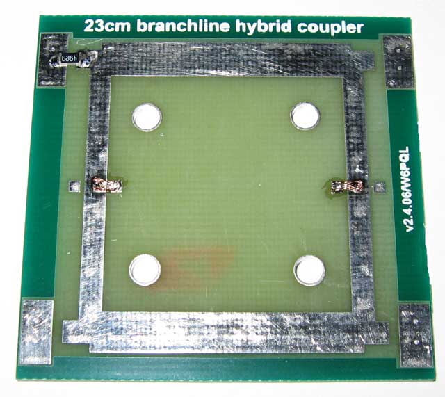
If you are combining modules, refer to this setup of one of the FR4 input couplers. Note the jumpers on one (each) of the smaller transmission lines. This jumper adds compensation to balance the outputs. FR4 is not always predictable (lots vary quite a bit), so I designed some compensating adjustments into the layout. This lot required the use of one of the trimmer pads (on each side). Jumper to the trace with a small wire or braid as shown. The terminating resistor for the isolated port is also shown. Place this on the upper left port as pictured.
When mounting this board, only two of the 4 mounting holes are
needed. Upper left and lower right, or vice-versa, is recommended.
 This
is one of the low-loss Teflon output couplers. I didn't have a way to plate it, so on
this one, I attempted to tin with solder. It just came out lumpy, so I left the
rest of them alone...they perform just the same, plated or not.
This
is one of the low-loss Teflon output couplers. I didn't have a way to plate it, so on
this one, I attempted to tin with solder. It just came out lumpy, so I left the
rest of them alone...they perform just the same, plated or not.
This picture is intended to show where the 20w isolation resistor should be placed, and how to attach your coax lead-ins. As you can see, I didn't solder anything in place yet; I just wanted to show how I intended to do it.
The outer of the coax can be soldered directly to the mounting foot, which is a plated-through tab attached to the back side of the board. Of course, the center conductor should be soldered to the trace. Leave about 1mm spacing between the outer conductor and the board edge.
You'll also notice that the mounting tabs raise the board up a bit so that it will be in the proper position to receive the tab on the 20w resistor. Using all 4 mounting holes on the coupler is recommended. The mounting hole for the 20w termination is not optional, you must use it.
These Teflon couplers can handle up to 350w at 1296.
Below is a suggested mechanical layout for a
2-module
amplifier, showing how most of the major components can be mounted to the
heat sink. When I tested this amplifier, it produced 65w with just 250mw drive.
I set each module to idle at 2a (4a for the pair), and at 65w out it drew 18a at
13.5v. Raising the voltage to 14.0 brought the output up to 70w.
Note the use of .085 semi-rigid coax for the jumpers. UT-141 will be difficult to work with in such short lengths; the .085 was hard enough to bend as it is, and will handle the power easily. Using flexible coax is OK, but it is less reliable on 23cm.
The 60w amplifier featured on the main web site describes a turn-key amplifier.
